Tutorial 6: IO part 2
Note
This is for practice, not for marks. Treat this as additional study material to help you develop your knowledge and skills on these topics. During the tutorial session, the TA will explain how to solve these problems.
For this tutorial, we will use hardware aspects of IO as seen in Lecture 4 (IO), slides 44–91.
Question 1
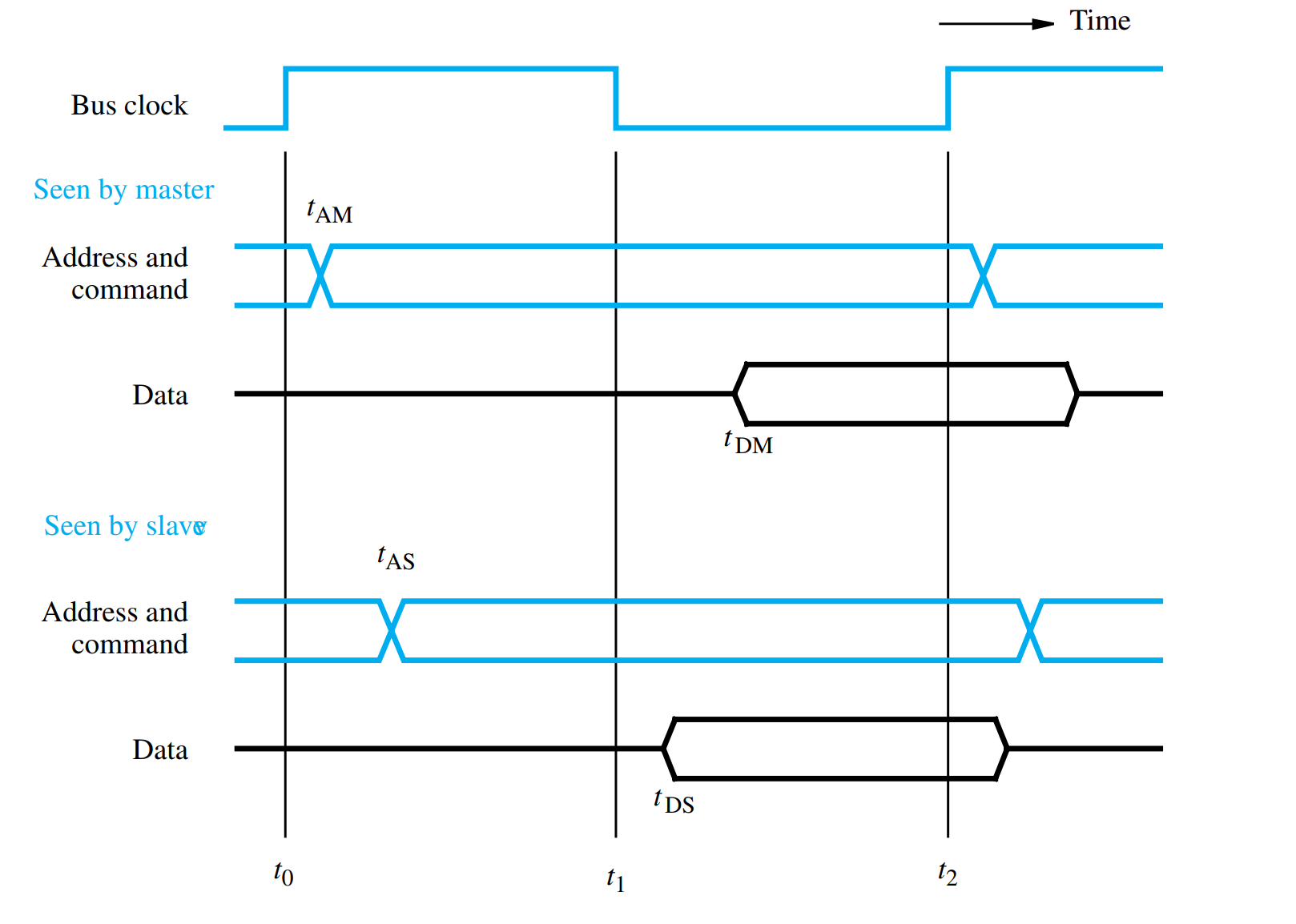
The I/O bus of a computer uses the synchronous protocol shown in Figure 7.4. Maximum propagation delay on this bus is 4 ns. The bus master takes 1.5 ns to place an address on the address lines. Slave devices require 3 ns to decode the address and a maximum of 5 ns to place the requested data on the data lines. Input registers connected to the bus have a minimum setup time of 1 ns. Assume that the bus clock has a 50% duty cycle; that is, the high and low phases of the clock are of equal duration. What is the maximum clock frequency for this bus?
Question 2
Design an output interface circuit for a synchronous bus that uses the protocol given in the Figure in Question 1. When data are written into the data register of this interface, the interface sends a pulse with a width of one clock cycle on a line called New-data. This pulse lets the output device connected to the interface know that new data are available.
Question 3
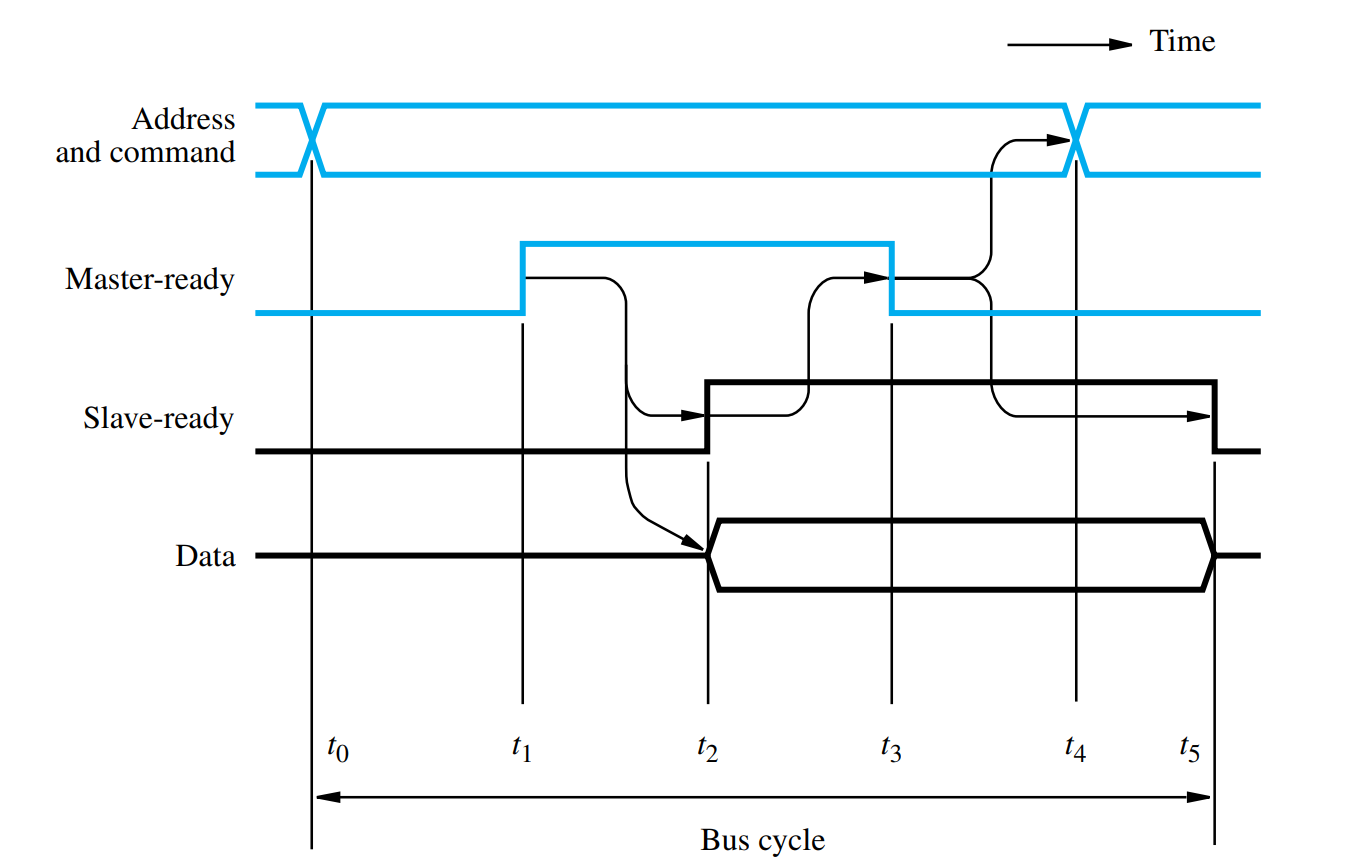
Handshake control of data transfer using an input operation.
How is the timing diagram in Figure 7.6 affected as the distance between the processor and the I/O device increases?
Question 4

A UART uses start-stop transmission to communicate as shown in the figure above. Explain how this communications works and why there isn’t a need for clock synchronization. Additionally, change the data-packet so it has some level of error checking.