Lab 3
In this lab we will use the high level I/O capabilities of the DE1-SoC simulator to
display pixels and characters using the VGA controller, and
accept keyboard input via the PS/2 port.
For each of these topics, we will create a driver. We will test the drivers both individually and in tandem by means of test applications.
1. Drawing things with VGA
The DE1-SoC computer has a built-in VGA controller that can render pixels, characters or a combination of both. The authoritative resource on these matters is Sections 4.2.1 and 4.2.4 of the DE1-SoC Computer Manual. This section of the lab provides a quick overview that should suffice for the purpose of completing this lab.
To render pixels, the VGA controller continuously reads the pixel buffer, a
region in memory starting at 0xc8000000 that contains the color value
of every pixel on the screen. Colors are encoded as 16-bit integers that reserve
5 bits for the red channel, 6 bits for the green channel and 5 bits for the blue
channel. That is, every 16-bit color is encoded like so:
15 … 11 |
10 … 5 |
4 … 0 |
|---|---|---|
Red |
Green |
Blue |
The pixel buffer is 320 pixels wide and 240 pixels high. Individual pixel colors
can be accessed at 0xc8000000 | (y << 10) | (x << 1), where x and
y are valid x and y coordinates.
As previously hinted, we can also render characters. To do so, we will use the
character buffer, which is analogous to the pixel buffer, but for characters.
The device’s VGA controller continuously reads the character buffer and renders
its contents as characters in a built-in font. The character buffer itself is a
buffer of byte-sized ASCII characters at 0xc9000000. The buffer’s has a
width of 80 characters and a height of 60 characters. An individual character can
be accessed at 0xc9000000 | (y << 7) | x.
Task: Create a VGA driver
To provide a slightly higher-level layer over the primitive functionality offered by the pixel and character buffers, we will create a driver. That is, a set of functions that can be used to control the screen.
To help get you started, we created an application that uses such functions to draw
a testing screen. Your job is to create a set of driver functions to support the
application. Download vga.s and augment it with the following
four functions:
VGA_draw_point_ASMdraws a point on the screen with the color as indicated in the third argument, by accessing only the pixel buffer memory. Hint: This subroutine should only access the pixel buffer memory.VGA_clear_pixelbuff_ASMclears (sets to 0) all the valid memory locations in the pixel buffer. It takes no arguments and returns nothing. Hint: You can implement this function by callingVGA_draw_point_ASMwith a color value of zero for every valid location on the screen.VGA_write_char_ASMwrites the ASCII code passed in the third argument (r2) to the screen at the (x, y) coordinates given in the first two arguments (r0 and r1). Essentially, the subroutine will store the value of the third argument at the address calculated with the first two arguments. The subroutine should check that the coordinates supplied are valid, i.e., x in [0, 79] and y in [0, 59]. Hint: This subroutine should only access the character buffer memory.VGA_clear_charbuff_ASMclears (sets to 0) all the valid memory locations in the character buffer. It takes no arguments and returns nothing. Hint: You can implement this function by callingVGA_write_char_ASMwith a character value of zero for every valid location on the screen.
Their C signatures are as follows:
void VGA_draw_point_ASM(int x, int y, short c);
void VGA_clear_pixelbuff_ASM();
void VGA_write_char_ASM(int x, int y, char c);
void VGA_clear_charbuff_ASM();
Notes:
Use suffixes
BandHwith the assembly memory access instructions in order to read/modify the bytes/half-words of the memory contents.You must follow the conventions taught in class. If you do not, then the testing code in the next section will be unlikely to work.
Testing the VGA driver
To test your VGA driver, run your finished assembly file. You can inspect the VGA output visually using the VGA pixel buffer tab under the Devices panel of the simulator.
If you implemented your driver correctly, compiling and running the program will draw the following image.

2. Reading keyboard input
For the purpose of this lab, here’s a high level description of the PS/2 keyboard protocol. For a more comprehensive resource, see Section 4.5 (pp. 45-46) of the DE1-SoC Computer Manual.
The PS/2 bus provides data about keystroke events by sending hexadecimal numbers called scan codes, which for this lab will vary from 1-3 bytes in length. When a key on the PS/2 keyboard is pressed, a unique scan code called the make code is sent, and when the key is released, another scan code called the break code is sent. The scan code set used in this lab is summarized by the table below. (Originally taken from Baruch Zoltan Francisc’s page on PS/2 scan codes.)
KEY |
MAKE |
BREAK |
KEY |
MAKE |
BREAK |
KEY |
MAKE |
BREAK |
||
|
|
|
|
|
|
|
|
|
||
|
|
|
|
|
|
|
|
|
||
|
|
|
|
|
|
|
|
|
||
|
|
|
|
|
|
|
|
|
||
|
|
|
|
|
|
|
|
|
||
|
|
|
|
|
|
|
|
|
||
|
|
|
|
|
|
|
|
|
||
|
|
|
|
|
|
|
|
|
||
|
|
|
|
|
|
|
|
|
||
|
|
|
|
|
|
|
|
|
||
|
|
|
|
|
|
|
|
|
||
|
|
|
|
|
|
|
|
|
||
|
|
|
|
|
|
|
|
|
||
|
|
|
|
|
|
|
|
|
||
|
|
|
|
|
|
|
|
|
||
|
|
|
|
|
|
|
|
|
||
|
|
|
|
|
|
|
|
|
||
|
|
|
|
|
|
|
|
|
||
|
|
|
|
|
|
|
|
|
||
|
|
|
|
|
|
|
|
|
||
|
|
|
|
|
|
|
|
|
||
|
|
|
|
|
|
|
|
|
||
|
|
|
|
|
|
|
|
|
||
|
|
|
|
|
|
|
|
|
||
|
|
|
|
|
|
|
|
|
||
|
|
|
|
|
|
|
|
|
||
|
|
|
|
|
|
|
|
|
||
|
|
|
|
|
|
|
|
|
||
|
|
|
|
|
|
|
|
|
||
|
|
|
|
|
|
|
|
|
||
|
|
|
|
|
|
|
|
|
||
|
|
|
|
|
|
|
|
|
||
|
|
|
|
|
|
|
|
|
||
|
|
|
|
|
|
|
|
|
||
|
|
|
|
|
Two other parameters involved are the typematic delay and the typematic rate. When a key is pressed, the corresponding make code is sent, and if the key is held down, the same make code is repeatedly sent at a constant rate after an initial delay. The initial delay ensures that briefly pressing a key will not register as more than one keystroke. The make code will stop being sent only if the key is released or another key is pressed. The initial delay between the first and second make code is called the typematic delay, and the rate at which the make code is sent after this is called the typematic rate. The typematic delay can range from 0.25 seconds to 1.00 second and the typematic rate can range from 2.0 cps (characters per second) to 30.0 cps, with default values of 500 ms and 10.9 cps respectively.
Task: Create a PS/2 driver
The DE1-SoC receieves keyboard input from a memory-mapped PS/2 data
register at address 0xff200100. Said register has an
RVALID bit that states whether or not the current contents
of the register represent a new value from the keyboard. The
RVALID bit can be accessed by shifting the data register
15 bits to the right and extracting the lowest bit, i.e.,
RVALID = ((*(volatile int *)0xff200100) >> 15) & 0x1.
When RVALID is true, the low eight bits of the PS/2 data
register correspond to a byte of keyboard data.
The hardware knows when you read a value from the memory-mapped PS/2 data register and will automatically present the next code when you read the data register again.
For more details, see Section 4.5 (pp. 45-46) of the DE1-SoC Computer Manual.
Download ps2.s. This assembly file implements a
program that reads keystrokes from the keyboard and writes the PS/2
codes to the VGA screen using the character buffer. Copy your VGA
driver into ps2.s. Then implement a function that adheres to
the following specifications:
Name:
read_PS2_data_ASMInput argument (r0): A memory address in which the data that is read from the PS/2 keyboard will be stored (pointer argument).
Output argument (r0): Integer that denotes whether the data read is valid or not.
Description: The subroutine will check the
RVALIDbit in the PS/2 Data register. If it is valid, then the data from the same register should be stored at the address in the pointer argument, and the subroutine should return 1 to denote valid data. If theRVALIDbit is not set, then the subroutine should simply return 0.
read_PS2_data_ASM’s C declaration is as follows:
int read_PS2_data_ASM(char *data);
Testing the PS/2 driver
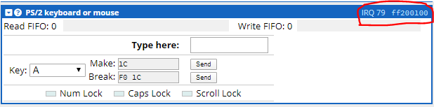
To verify that the PS/2 driver is working correctly, you can type into the simulator’s PS/2 keyboard device and verify that the bytes showing up on the screen correspond to the codes you might expect from the table in this section’s introduction.
If you implemented your PS/2 and VGA drivers correctly, then the
program will print make and break codes whenever you type in the
simulator’s keyboard input device. Make sure to use the keyboard
device that says ff200100.
Note: If you did not manage to implement a working VGA driver,
then you can still get credit for the PS/2 driver by replacing
write_byte with the implementation below. It will write
PS/2 codes to memory address 0xfff0. Delete all calls
to VGA driver functions and delete the write_hex_digit
function to ensure that your code still compiles.
write_byte:
        push    {r3, r4, lr}
        ldr     r4, =0xfff0
        and     r3, r3, #0xff
        str     r3, [r4]
        pop     {r3, r4, pc}
3. Putting everything together: Vexillology
We will now create an application that paints a gallery of flags. The user can use keyboard keys to navigate through flags. Pressing the D key will prompt the application to show the next flag. Similarly, pressing the A key will prompt the application to show the previous flag. Pressing A when at the first flag or D when at the last flag cycles to the last or first flag, respectively.
Download flags.s. This file implements
an input loop that reads keystrokes from the keyboard, tests
if they are A or D key presses, and cycles flags accordingly.
It also implements a function that draws the flag of Texas.
Your task is twofold:
Include your VGA and PS/2 driver functions.
Implement flag painting logic for two other flags by rewriting
draw_real_life_flaganddraw_imaginary_flag. One flag must be a real-life flag and another flag can be a flag you designed yourself.
Hint: The starter code includes the draw_rectangle
and draw_star functions. You can use these functions to
draw any flag that consists of rectangles and stars. This
encompasses many flags, from the flags of the US to France
and even China.
draw_rectangledraws a rectangle. It takes five arguments. The first four arguments are stored in registers r0 through r3. The fifth argument is stored on the stack at address[sp].draw_rectangle’s signature is:/** * Draws a rectangle. * @param x The x coordinate of the top left corner of the rectangle. * @param y The y coordinate of the top left corner of the rectangle. * @param width The width of the rectangle. * @param height The height of the rectangle. * @param c The color with which to fill the rectangle. */ void draw_rectangle(int x, int y, int width, int height, int c);
draw_stardraws a star. It takes four arguments, stored in registers r0 through r3. Its signature is:/** * Draws a star. * @param x_center The x coordinate at which the star is centered. * @param y_center The y coordinate at which the star is centered. * @param radius The star's radius. * @param c The star's color. */ void draw_star(int x_center, int y_center, int radius, int c);
Hint: The flag of Texas as drawn by the starter code should look like the image below. If it doesn’t, then your VGA driver might be faulty.

Grading and Report
Your grade will be evaluated through the deliverables of your work during the demo (70%) (basically showing us the working programs), your answers to the questions raised by the TA’s during the demo (10%), and your lab report (20%).
Grade distribution of the demo:
Part 1: VGA driver (30%).
Part 2: PS/2 driver (20%).
Part 3: Flag gallery application (20%).
Write up a short report (max 5 pages in total) that should include the following information.
A brief description of each part completed (do not include the entire code in the body of the report).
The approach taken (e.g., using subroutines, stack, etc.).
The challenges faced, if any, and your solutions.
Possible improvement to the programs.
Your final submission should be submitted on myCourses. The deadline for the submission and the report is Friday, 4 December 2020. A single compressed folder should be submitted in the .zip format, that contains the following files:
Your lab report in pdf format: StudentID_FullName_Lab3_report.pdf
The assembly program for Part 1: vga.s
The assembly program for Part 2: ps2.s
The assembly program for Part 3: flags.s
A screenshot of your real-life flag and a screenshot of your imaginary flag: real-life-flag.png and imaginary-flag.png. Make sure to take screenshots that include the simulator UI, so we can verify that your pictures were created by the simulator.
Important
Note that we will check every submission (code and report) for possible plagiarism. All suspected cases will be reported to the faculty. Please make sure to familiarize yourself with the course policies regarding Academic Integrity and remember that all the labs are to be done individually.
The demo will take place via Zoom between 24 Nov - 30 Nov 2020 on the day of you assigned lab session day. We will provide a registration system for the demo the week before. You will need to answer live questions during the demo with your screen shared to onstrate the working program.